BENDIX BW1560 Uživatelský manuál Strana 1
Procházejte online nebo si stáhněte Uživatelský manuál pro Vzduchové kompresory BENDIX BW1560. BENDIX BW1560 User's Manual Uživatelská příručka
- Strana / 36
- Tabulka s obsahem
- KNIHY
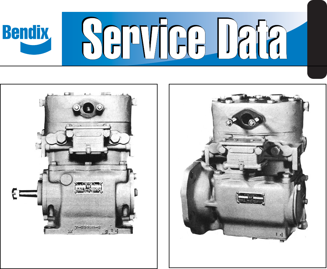
- 600 Air Compressor 1
- NAME PLATE 2
- OPERATION 3
- AIR CLEANER MAINTENANCE 5
- AIR LEAKAGE TESTS 6
- REMOVING AND INSTALLING 6
- DISASSEMBLY 6
- PREVENTATIVE MAINTENANCE 7
- FIGURE 13 - TU-FLO 8
- FIGURE 14 - TU-FLO 8
- LUBRICATION 9
- INSPECTION OF PARTS 9
- ASSEMBLY 11
- TABULATED DATA 13
- COMPRESSOR TROUBLESHOOTING 13
- THESE INSTRUCTIONS TO AVOID 13
- PERSONAL INJURY OR DEATH: 13
- Test Procedures 15
- (Supply Reservoir) 16
- Vehicle Used for: 17
- BASIC Test 18
- (Bendix kit P/N 5013711) 20
- Kinked discharge line shown 24
- Dash gauges 24
- Partly collapsed 24
- Technician removes 26
- Testing for leaks 27
- Compressor Air Dryer 28
- Discharge Inlet 28
- Fitting Fitting 28
- Tests (continued) 29
- Air System Inspection Cup 30
- (BASIC) Test Information 30
- STEP A - Select one: 31
- (if the number of days is 32
- Technical Bulletin 33
Shrnutí obsahu
1®Bendix® TU-FLO® 600 Air CompressorSD-01-336GENERALThe function of the air compressor is to build up and maintainthe air pressure required to operate
10CYLINDER BLOCKCheck for cracks or broken lugs on cylinder block. Alsocheck unloader bore bushings to be sure they are not worn,rusted or damaged. If
11CRANKSHAFTCheck crankshaft screw threads, keyways, tapered endsand all machined and ground surfaces for wear, scores, ordamage. Crankshaft journals
12Position a rear end cover gasket, when used, over the rearend of the crankcase, making sure the oil hole in the gasketlines up with the oil hole in
13A compressor efficiency or build-up test can be run which isnot too difficult. An engine lubricated compressor must beconnected to an oil supply lin
145. Following the vehicle manufacturer’srecommended procedures, deactivate the electricalsystem in a manner that safely removes all electricalpower f
*This guide is only for vehicles that use desiccant air dryers.The guide consists of an introduction to air brake charging systemcomponents, a table s
16Introduction to the Air Brake Charging SystemPowered by the vehicle engine, the air compressorbuilds the air pressure for the air brake system. Thea
17Compressor with up to 25% duty cycleFootnotes:1 With increased air demand the air dryer cartridge needs to be replaced more often.2 Use the drain va
18üAir Brake Charging System TroubleshootingHow to use this guide:1.0 Oil Test CardResultsNot a valid test.Discontinue using this test.Do not use thi
Symptom: What it may indicate: What you should do:192.2 Oil leakingfrom compressor:(a)Excessive leak at head gasket.(b)Leak at bottom cover plate.(c)
2FIGURE 2 - TU-FLO® 600 AIR COMPRESSOR SECTIONALVIEWFIGURE 3 - TU-FLO® 600 AIR COMPRESSOR PISTON/PINDESIGNFIGURE 1 - FLANGE CONFIGURATIONSWRISTPINBUSH
204.0 Oil in Supply orService Reservoir(air dryer installed)(If a maintained Bendix®PuraGuard® system filteror Bendix® PuraGuard®QC™ oil coalescing f
Symptom: What it may indicate: What you should do:21(e)Air compressor discharge and/orair dryer inlet temperature too high.(f) Insufficient coolant fl
Symptom: What it may indicate: What you should do:22(i) Poorly filtered inlet air (poor airquality to compressor).(j) Governor malfunction or setting
Symptom: What it may indicate: What you should do:238.0 Oil in ping tankor compressor dis-charge aftercooler.Air brake charging system isfunctioning
Symptom: What it may indicate: What you should do:24(g)Restricted air inlet (not enough airto compressor).ð Check compressor air inlet line forrestric
Symptom: What it may indicate: What you should do:2510.0 Air chargingsystem doesn’tbuild air.(a)Governor malfunction*.(b) Restricted discharge line.(
Symptom: What it may indicate: What you should do:2615.0 Compressorconstantly cycles(compressorremains unloadedfor a very shorttime.)(a)Air brake cha
Symptom: What it may indicate: What you should do:27This guide attempts to cover mostcompressor system problems. Here aresome rare sources of problems
28TestsExterior leaks at the head gasket are not a sign that oil is being passedinto the air charging system. Oil weepage at the head gasket does not
1. Ensure that the governor control line from thereservoir is located at or near the top of thereservoir. (This line, if located near the bottomof the
3FIGURE 5FIGURE 6DISCHARGEVALVEPISTONSTROKETO GOVERNORINTAKESTRAINERUNLOADERPLUNGERINLET VALVETO RESERVOIRINTAKEDISCHARGEVALVEPISTONSTROKETO GOVERNORI
HighSTART BASIC TESTIs this atransit vehicle, bulkunloader, or has morethan 5 axles?YES, this is a highair usevehicle.NO, this is a low airuse vehicle
Footnote 1: Note: Typical air dryer cartridge replacement schedule is every 3 yrs/ 300K miles for low air use vehicles and every year/100K miles forhi
Park the vehicle on level ground and chock wheels. Build system pressure to governor cut-outand allow the pressure to stabilize for one minute.1: Obse
33Technical BulletinBulletin No.: TCH-008-021 Effective Date: 11/1/92 Page: 1 of 2Subject: Air Brake System - Cold Weather Operation TipsAs the cold w
34Bulletin No.: TCH-008-021 Effective Date: 11/1/92 Page: 2 of 2High Duty Cycle Vehicles (City Transit Coaches, Refuse Haulers, Etc.)The maximum disch
Technical BulletinBulletin No.: TCH-008-022 Effective Date: 1/1/1994 Page: 1 of 1Subject: Additional Cold Weather Operation Tips for the Air Brake Sys
BW 1560 © 2004 Bendix Commercial Vehicle Systems LLC All rights reserved. 9/2004 Printed in U.S.A.36
4COMPRESSOR & THE AIR BRAKE SYSTEMGENERALThe compressor is part of the total air brake system, morespecifically, the charging portion of the air b
5DISCHARGE LINE TEMPERATUREWhen the temperature of the compressed air that entersthe air dryer is within the normal range, the air dryer canremove mos
6AIR LEAKAGE TESTSLeakage past the discharge valves can be detected byremoving the discharge line, applying shop air back throughthe discharge port an
7The discharge valve cap nuts should be inspected for wearand replaced if excessive peening has occurred. Todetermine if excessive peening has occurre
8FIGURE 13 - TU-FLO® 600 AIR COMPRESSOR CYLINDER BLOCK ASSEMBLYFIGURE 14 - TU-FLO® 600 AIR COMPRESSOR CRANK CASE ASSEMBLY
9CYLINDER HEAD ASSEMBLYRemove all carbon deposits from discharge cavities and allrust and scale from cooling cavities of cylinder head body.Scrape all
Související produkty a manuály pro Vzduchové kompresory BENDIX BW1560
 (35 stránky)
© 2020, manymanuals.cz. Všechna práva vyhrazena. | 0.020 s |
 Manymanuals.com
 Manymanuals.de
 Manymanuals.fr
 Manymanuals.it
 Manymanuals.pl
 Manymanuals.cz
 Manymanuals.es
 Manymanuals-pt.com
Komentáře k této Příručce